Sunday, May 8, 2011

File organization input-output devices

File Oraganization can be sequential, line sequential, indexed, or relative.
Sequential file organization
The chronological order in which records are entered when a file is created establishes the arrangement of the records. Each record except the first has a unique predecessor record, and each record except the last has a unique successor record. Once established, these relationships do not change.
The access (record transmission) mode allowed for sequential files is sequential only.
Line-sequential file organization
Line-sequential files are sequential files that reside on the hierarchical file system (HFS) and that contain only characters as data. Each record ends with a new-line character. The only access (record transmission) mode allowed for line-sequential files is sequential.

Indexed file organization
Each record in the file contains a special field whose contents form the record key. The position of the key is the same in each record. The index component of the file establishes the logical arrangement of the file, an ordering by record key. The actual physical arrangement of the records in the file is not significant to your COBOL program. An indexed file can also use alternate indexes in addition to the record key. These keys let you access the file using a different logical ordering of the records. The access (record transmission) modes allowed for indexed files are sequential, random, or dynamic. When you read or write indexed files sequentially, the sequence is that of the key values.
Relative file organization
Records in the file are identified by their location relative to the beginning of the file. The first record in the file has a relative record number of 1, the tenth record has a relative record number of 10, and so on. The access (record transmission) modes allowed for relative files are sequential, random, or dynamic. When relative files are read or written sequentially, the sequence is that of the relative record number.
Sequential-only devices
Terminals, printers, card readers, and punches are called unit-record devices because they process one line at a time. Therefore, you must also process records one at a time sequentially in your program when it reads from or writes to unit-record devices. On tape, records are ordered sequentially, so your program must process them sequentially. Use QSAM physical sequential files when processing tape files. The records on tape can be fixed length or variable length. The rate of data transfer is faster than it is for cards.
Direct-access storage devices
Direct-access storage devices hold many records. The record arrangement of files stored on these devices determines the ways that your program can process the data. When using direct-access devices, you have greater flexibility within your program, because your can use several types of file organization:

# Sequential (VSAM or QSAM)
# Line sequential (UNIX)
# Indexed (VSAM)
# Relative (VSAM)


Choosing file organization and access mode

# If an application accesses records (whether fixed-length or variable-length) only sequentially and does not insert records between existing records, a QSAM or VSAM sequential file is the simplest type.
# If you are developing an application for UNIX that sequentially accesses records that contain only printable characters and certain control characters, line-sequential files work best.
# If an application requires both sequential and random access (whether records are fixed length or variable length), a VSAM indexed file is the most flexible type.
# If an application inserts and deletes records randomly, a relative file works well. Consider the following guidelines when choosing access mode:
# If a large percentage of a file is referenced or updated in an application, sequential access is faster than random or dynamic access.
# If a small percentage of records is processed during each run of an application, use random or dynamic access.

Note: courtesy of IBM

Tuesday, April 12, 2011

Netezza Enterprise Stage in DataStage

Netezza Enterprise stage is a database stage. You can use this stage to write bulk data to Netezza Performance Server(NPS). The Netezza Enterprise stage uses the Netezza write operator (nzwrite) to write data to Netezza Performance Server.

The Netezza write operator sets up a connection to an external data source and inserts records into a table. The operator takes a single input data set. The write mode determines how the records of a data set are inserted into the table.
Netezza write operator:

The Netezza write operator writes data to Netezza Performance Server. Netezza does not provide a read operator and hence the data retrieved from the source database is saved in a data set. The Netezza enterprise stage reads data from the data set and writes it to the Netezza Performance Server database.
Netezza data load methods:
The Netezza write operator employs two alternate methods to load data to Netezza Performance Server. You can write data to a Netezza Performance Server database either by using a nzload load utility or by writing data to an external table before writing it to the database.
nzload method:
You can use this load method if the data in the source database is consistent; that is, it implements a single character set for the entire database. Also the input schema for the nzload must be the same as that of the target table in the Netezza Performance Server database. The prerequisite to use the nzload method is that, nzclient utilities and ODBC functionality must be installed on the same computer as the IBM InfoSphere Information Server engine.
External table method:
If the data source that you want to read contains default values for table columns and uses variable format for data encoding such as UTF-8. You can write the data to an external table before loading it into the Netezza Performance Server database.
Write modes

Append:
Appends new rows to the specified table. To use this mode, you must have TABLE CREATE and INSERT privileges on the database that is being written to. Also the table must exist and the record schema of the data set must be compatible with the table. This mode is the default mode.
create
Creates a new table in the database. To use this mode, you must have TABLE CREATE privileges. If a table already exists with the same name as the one that you want to create, the step that contains this mode ends in error. The table is created with simple default properties. To create a table that is partitioned, indexed, in a non-default table space, or to create a customized table, you must use the -createstmt option with your own create table statement.
Replace
Drops the existing table and creates a new one in its place. To use this mode, you must have TABLE CREATE and TABLE DELETE privileges. If another table exists with the same name as the one that you want to create, the existing table is overwritten.
Truncate
Retains all the attributes of a table (including its schema), but discards the existing records and appends new records into the table. To use this mode, you must have DELETE and INSERT privileges on that table.

Monday, April 11, 2011

Netezza system

A Netezza system consists of multiple hardware and software components working together to provide performance and reliability. The NPS models include configurations with one or more hardware racks. Within each rack are numerous components that work together to provide the asymmetric massively parallel processing of the NPS architecture. The key hardware components within an NPS include the following:
τ€˜ NPS Host
τ€˜ Snippet Processing Units
τ€˜ Snippet Processing Arrays
NPS Host
The NPS host, located within the NPS rack, controls and coordinates the activity of the NPS. It performs query optimization; controls table and database operations; consolidates and returns query results; and monitors the NPS system components to detect and report problems.
Snippet Processing Units
The Snippet Processing Unit (SPU) is the basic unit of processing and storage in the NPS.Each SPU is basically a standalone microcomputer, with a CPU, logic processors, memory,and disk storage.The SPU is an intelligent disk storage device, as it has logic to quickly search for the correct information and to return only the matching results of the portions of the data that are saved on its disk.An NPS system has many SPUs: up to 56,User database tables are distributed across all of the SPUs to allow for the parallel query processing.
Each SPU is responsible for managing a portion of your database and tables (called a primary partition), as well as for maintaining a copy of another SPU’s primary partition (called a mirror partition). If an SPU should fail, the mirror partition is used to create a new primary partition on a standby SPU within the system, which will then take the place of the failed SPU.
Snippet Processing Arrays
Snippet Processing Arrays (SPAs) are racks within the NPS system that contain up to 14 SPUs and have the power supplies, fans, and communication fabric that allows the SPUs to communicate with each other and with the NPS host. NPS systems contain at least two SPAs. If you add SPAs to the system to increase the number of SPUs, the SPAs are added in pairs. For each pair of SPAs, one of the 28 SPUs takes the role of a hot standby, ready to take the place of a failed SPU within the system.
NZSQL:

Commonly Used Command Options

nzload Command Options:

Friday, January 14, 2011

IBM InfoSphere Blueprint Director

InfoSphere™ Blueprint Director, you can define and manage a blueprint your information project landscape from initial sketches through delivery. Information integration and transformation is a part of every organization. Introduction of new systems or changes to infrastructure or business processes require that the information is restructured, moved, or distributed in new ways. All of these scenarios involve significant changes to the underlying information infrastructure.
InfoSphere Blueprint Director includes several major capabilities that enable governance teams to develop a common information blueprint:

> Creating project blueprints so that you can link blueprint elements to related artifacts. For example, you can connect elements to metadata and open IBM® InfoSphere Metadata Workbench from that element to view the referenced metadata. Similarly, you can use the included linkers to connect elements to data models (IBM InfoSphere Data Architect), ETL definitions (IBM InfoSphere DataStage®), measure and dimension models (IBM Cognos® Framework Manager), URLs (Web browsers), or any files and their associated applications.
> Extensible palette of domain elements for use in sketching information blueprints
> Free-form sketching to define, view, and manage information blueprints
> Linking of blueprint elements to metadata from the InfoSphere metadata repository (if you have a valid license for IBM InfoSphere Metadata Workbench), files, and assets accessible by URL
> Tagging blueprint elements with business glossary terms and creating conceptual models using business glossary terms (if you have a valid license for and have installed IBM InfoSphere Business Glossary Anywhere)
> Pre-built templates including a topology and method definition that support specific usage scenarios, such as business intelligence (BI) and warehousing, that correlate to a defined blueprint, such as a BI reference architecture

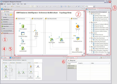
1.Palette
Lists a selection of blueprint elements that can be used in a project.
2.Diagram canvas
Provides a visualization area where you specify and view the blueprint. You can have multiple diagram windows opened at the same time, such as a diagram that represents the top-level diagram and drill down diagram views.
3.Method Browser pane
Shows the method outline. The detailed method content description is shown in the top center.
4.Outline pane
Shows a graphical representation of which part of the overall blueprint is currently shown in the canvas.
5.Blueprint Explorer pane
Shows an expandable list of all the elements that are contained in the blueprint specification.
6.Properties pane
Shows context-specific properties. For example, this pane shows the properties of a selected element on the diagram or the properties of a selected metadata entry in the asset browser.
Asset Browser pane
[upper right; content not shown]
Shows the list of assets from the metadata repository that you can drag onto the canvas. You must have a license for IBM InfoSphere Metadata Workbench and have the product installed (not necessarily on the same computer) in order to use this feature.
Business Glossary pane
[upper right; content not shown]
InfoSphere Blueprint Director provides consistency and connectivity to your information architecture solution by linking the solution overview and detailed design documents together, allowing all team members to understand the project as it evolves.
Creating a blueprint based on a template

You can use templates to create a blueprint that is based on a standard set best practices. Using templates results in a blueprint that follows a standard reference architecture and is associated with best practices to help guide team members through the process of creating a blueprint.
When you create a blueprint, reuse a standard template whenever possible to ensure consistency and completeness of your blueprint. Templates include method content that is linked to topology elements. Templates are delivered as .jar files, which should be placed in the plugins folder of your installation. For example, copy any blueprint templates into the BlueprintDirectorHome\plugins directory, where BlueprintDirectorHome is the directory where you installed IBM InfoSphere Blueprint Director.
If you have used an early version of InfoSphere Blueprint Director as part of an
early release program, you might have blueprint specifications that are saved as
*.lp_diagram or *.lp files. You can open these files by selecting the appropriate file type when opening a blueprint file. After you open the files, you can then save them in the current format, *.bpt.
1. Start the IBM InfoSphere Blueprint Director client.
2. Click File → New → Blueprint from the application main menu to begin creating a new blueprint.
3. Select the Create blueprint from template radio button.
4. Select the blueprint template that you want to use as a base for your new blueprint.
5. Click Finish to create the new blueprint.

Associating method elements with blueprint palette elements

When you create a blueprint that is based on a template, you can associate method elements with blueprint palette elements to provide contextual guidance on the development of solution artifacts. You can also explicitly associate methodology items from the Method Browser pane with blueprint elements.
The Method Browser visualizes a methodology in the context of a blueprint. You use the Method Browser pane to expose key phases, capability patterns, and activities of the method for a selected project based on a template. This view provides you with a high-level overview and guidance for the required steps in a particular project. When you define and manage a new project, you have access to the corresponding method in a hierarchical view for high-level phases and activities, plus detailed descriptions.
When you double-click a node in the Method Browser, a new window opens next to the diagram window that contains a detailed definition of the method element and recommended actions for that topic.

1. From the main menu, click View → Method Browser.
2. Select the method element from the Method Browser that you want to associate with a blueprint element.
3. Drag the method element onto the blueprint element that you want to create an association with on the drawing canvas.IBM InfoSphere Blueprint Director establishes an association between the method element and the blueprint element. The associated method step is indicated by a blue circle with an “m” next to the element:.When you click on this blue circle,you can view the list of available method elements.

Sunday, January 9, 2011

IBM InfoSphere Data integration with Salesforce

Salesforce is a leading on-demand customer relationship management (CRM) system. It offers a complete hosted solution for companies to manage their customer contacts, track sales orders, and streamline their sales processes. It also allows customers to tailor their software as a service, therefore gaining a competitive advantage.

IBM Information Server is an ideal solution to integrate and synchronize Salesforce CRM data with the business data stored within back end enterprise resource planning (ERP) systems and other data analytical applications.
Software products needed for designing ETL jobs for Salesforce.com


•IBM Information Server DataStage, which includes:
◦DataStage Client
◦DataStage Server
◦DataStage Metadata Repository
◦DataStage Domain Server
Information Server DataStage products can be installed separately on different hosts or installed on the same host.
•Information Server Pack for Salesforce.com (IS Salesforce Pack)
The IS Salesforce Pack is a companion product of the IBM Information Server. The pack has been developed to connect to Salesforce.com through Web services. The GUIs of the IS Salesforce Pack are installed on the DataStage Client. The runtime part of the pack is installed on the DataStage Server.
•Apache Axis
Apache Axis is an external component that is used to manage the transport layer of the IS Salesforce Pack. It contains libraries for the HTTP/HTTPS protocols
Apache Axis as external component


Architecture overview

Each software components in Figure 1 plays a different role in designing and executing the ETL jobs for Salesforce.com:

•The Information Server DataStage Client and IS Salesforce Pack GUI components provide a smart UI to allow users to design ETL jobs, import and export metadata, and set up data operations to be performed on Salesforce.com
•The Information Server DataStage Server and IS Salesforce Pack server components enable users to schedule and run the ETL jobs.
•The Information Server Domain Server manages Information Server user accounts and authorization.
•The Information Server Metadata Repository is a single repository database for storing and sharing metadata definitions.
The Information Server Salesforce Pack includes three major components:

•Salesforce metadata browser for browsing and importing the definitions of the Salesforce objects from Salesforce.com to DataStage.
•Salesforce Load Stage for loading data from non-Salesforce data sources to Salesforce.com. It is a Salesforce certified loading solution.
•Salesforce Extract Stage for extracting data from Salesforce.com to non-Salesforce data sources. It is a Salesforce certified extraction solution. Both Salesforce load and extract stages depend on the Salesforce.com Web service APIs.
Salesforce metadata browser

The pack has a smart metadata browser. It supports browsing both Salesforce objects and custom objects created by Salesforce users. It is capable of importing the selected object definitions from the Salesforce back to IBM Information Server for future usages. The metadata browser displays only the objects and fields that are applicable to the user-selected data operations. Below Figure shows the metadata browser for the query operation. The metadata browser shows only the Salesforce objects on which users can perform query operations.

Metadata browser and Upsertable objects in end-user's Salesforce account:

As shown in two Figure, different sets of objects, including custom objects, are displayed based on user-selected operations. This feature eliminates the guessing game for the end user regarding what operation is associated with which object and the reverse.

The metadata browser shows not only the Salesforce objects but also the field attributes related to those objects. It further simplifies the end userΓ’€™s task at the DataStage job design phase. In the below Figure, the Opportunity object is selected with UPSERT operation. Only the fields in the object that are qualified for the UPSERT operation are displayed.
Opportunity fields with Upsert operation

In the below Figure, the same Opportunity object is selected with the Query operation. Compared to above Figure , a different set of fields is shown for the Opportunity object. Only the fields in the object that are qualified for the Query operation are visible.
Opportunity fields with Query Operation:


The metadata browser imports the Salesforce object and field definitions into DataStage. You first select the interested Salesforce object and its data fields, as shown in below Figure . Then you click Import to convert the selected Salesforce object definitions to the DataStage table definitions. The created table definition is shown in Figure 7. You can also save the table definitions to the DataStage repository for future usages.
Importing Salesforce metadata:


Saving the metadata definitions in Datastage:

Sunday, January 2, 2011

Oracle Business Intelligence ( OBIEE )

Oracle Business Intelligence ( OBIEE ):
> Client
> Oracle BI Prensentation Services
> Oracle BI Server
> Oracle BI repository
> Data sources

Clients:
Provide access to business intelligence information
> Oracle BI Answers: Is a set of graphical tools used to build, view, and modify Oracle BI requests.
> Oracle BI Interactive Dashboards: Display the results of Answers requests and other items
> Oracle BI Administration Tool: Is used to build and Oracle BI repository