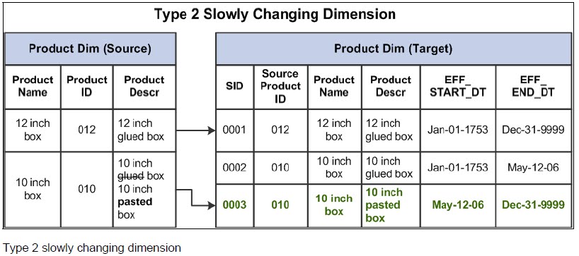
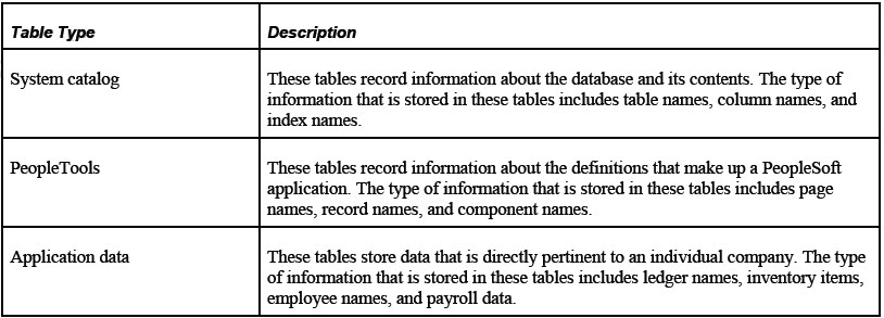
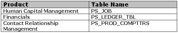
WTX Map node overview
The WTX Map node is a component of WebSphere TX for Message Broker, which is packaged with WebSphere TX for Integration Servers and is available for use in Message Broker message flows. It runs a WebSphere TX map within a message flow. The WTX Map node uses one or more Message Broker message trees as its input, runs a WebSphere TX map that you specify, and creates one or more Message Broker message trees as its output.
The map run by the WTX Map node can be either a compiled map that is pre-deployed to the broker, or a source map that is compiled when the message flow is added to a broker archive (BAR) file and deployed as part of broker archive deployment. The map can have multiple input cards, but the WTX Map node only has a single input terminal. The message arrives at the input terminal and then the proper pre-assigned input card picks up the message internally and maps it.
If the message tree that arrives at the input terminal consists of a single message, the input card that receives the message must be chosen. If the arriving message tree is a message collection containing multiple messages, then each message in the collection is delivered to the appropriate input card. Then the WTX Map node runs the map.
WebSphere TX comes from a different background and has different strengths compared to Message Broker. Its heritage is in processing large file structures, and it can provide complex data transformation capabilities for all structured and semi-structured data formats, including mixed types. Also, WebSphere TX is better suited to handling custom tagged message formats or mixed tagged and binary. Finally, it is well suited for large file structures. Together, WebSphere TX and Message Broker provide a combination unique in the marketplace for its breadth and depth.
Using the WTX Map node within a message flow
When you develop a message flow, you can set up a WTX Map node that runs a map that has a single input card or multiple input cards. The activities for using a WTX Map node within a message flow include:
•Creating a Map
•Developing a message flow that uses the WTX Map node
•Deploying the message flow
◦Creating and building a BAR file
◦Deploying the BAR file
◦If you are using a precompiled map, deploying the map
•Running your message flow
After the message flow is deployed, Message Broker starts the message flow automatically, and the following actions result:
•The message flow runs when an input node receives an input message bit stream.
•A parser parses the input bit stream into an input message tree.
•A WTX Map node receives the input message tree and runs the map.
•The map transforms the data in the input message tree and creates one or more output message trees.
•The output message trees can be processed by other nodes in the message flow.
Creating a map
Figure 1. WebSphere TX development perspective selection
Introduction to the Map DesignerUse the Map Designer through the WebSphere TX development perspective (shown below) to develop maps that define input and output specifications and mapping rules for
data transformation: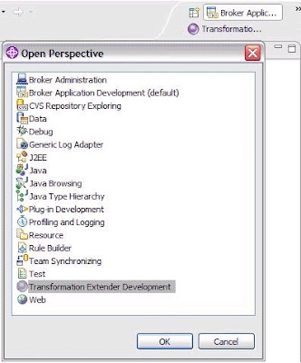
The Map Designer uses the definitions of data stored in the type trees (created using the Type Designer) to specify the transformation logic in the form of map rules. Map rules operate on input data objects and build output data objects. The map can be built for specific platforms, and then run on that platform to perform data transformation.
Using the Map Designer
To use the Map Designer, you must already have the type trees that define your data. The Map Designer uses the data object definitions stored in those type trees. The Map Designer is used to:
•Create maps to specify the logic to transform the input data to the desired output data.
•Identify the source and data objects of the input data.
•Validate and resolve the source data type properties defined in the Type Designer.
•Identify the target and data objects of the output data.
•Specify and build the output data according to the map rules.
•Provide information about data validation by generating trace files.
•View the run results of the map execution.
Figure 2. Map Designer in Message Broker Toolkit.
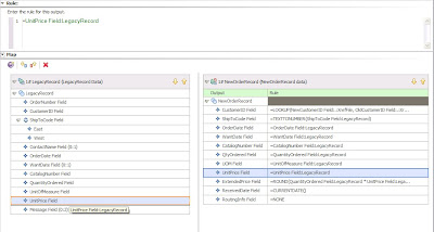
Figure 3. Example map design of input card
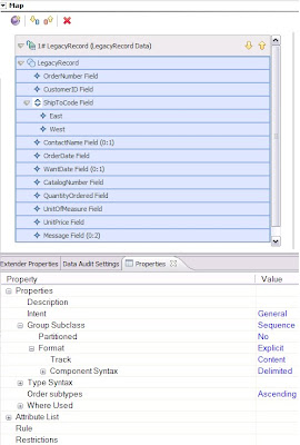
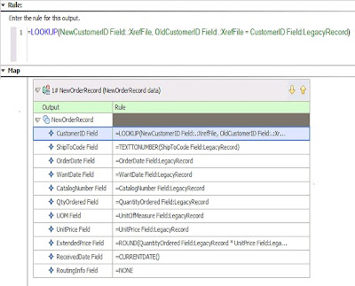
Figure 4. Example map design of output card
After defining data objects and their properties in the Type Designer, you define a map in the Map Designer, where map cards specify the input source and the output target.
Developing a message flow using the WTX Map node
In a message flow, there are several different ways to use the WTX Map node:
With a source map and a single input
Develop a message flow with a WTX Map node specified with a source map that, at run time, is triggered to run by a single input.
With a precompiled map and a single input
Develop a message flow with a WTX Map node specified with a precompiled map that, at run time, is triggered to run by a single input.
With a source map and multiple inputs
Develop a message flow with a WTX Map node specified with a source map that, at run time, is triggered to run by multiple inputs.
With a precompiled map and multiple inputs
Develop a message flow with a WTX Map node specified with a precompiled map that, at run time, is triggered to run by multiple inputs.
Message flow development
Using the WTX Map node with a source map and a single input
The map can have many input cards, but only one nominated card receives data from the message flow, while each of the other cards pulls data directly from their adapter. The map can also have many output cards. Cards that are connected to the message flow propagate data to the flow, while each of the unconnected cards send data directly to their adapter. To develop a simple message flow that demonstrates this scenario, use the following steps. They assume that you used Map Designer to create a source map (.mms) file containing an executable map with one or more input cards, and one or more output cards.
1.Create a new message flow project in the Message Broker Application Development perspective.
2.Create a new message flow in the project: select Use default broker schema or provide your own schema name to qualify the message flow name.
3.Drag a WTX Map node from the palette onto the canvas for your message flow. The node initially has no output terminals, and one failure terminal. The WebSphere TX Drawer and WTX Map node palette are shown in Figure 5:
Figure 5. WTX Map node in Message Broker Toolkit
4.Navigate to the Properties view, shown in Figure 1 above.
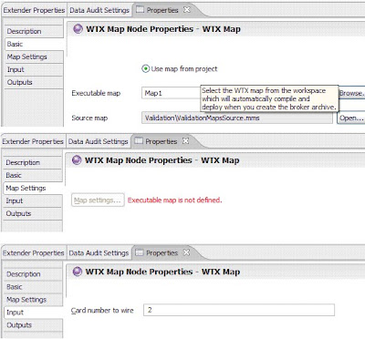
5.On the Basic tab of the WTX Map node, select the source map.
6.On the Input tab of the WTX Map node, select the map card that receives the input. Important properties of the WTX Map node are shown in Figure 6:
Figure 6. Properties of WTX Map node
7.Drag an input node such as a FileInput node or an MQInput node to the left of the WTX Map node, and connect the out terminal of the input node to the in terminal of the WTX Map node. The message from the input node overrides the adapter of the map's selected input card.
8.Configure the input node with the necessary transport-related properties.
9.On the Input Message Parsing tab of the input node, configure the message template properties to describe the format of the input message. Select the domain from the list of supported message domains.
10.Drag an output node such as a FileOutput node or an MQOutput node to the right of the WTX Map node, and connect one of the output terminals of the WTX Map node to the in terminal of the output node. Connecting the output terminal overrides the adapter of the corresponding output card.
11.Configure the output node with the necessary transport-related properties.
12.On the Outputs tab of the WTX Map node, configure properties to describe the format of the output message propagated by the output card:
1.Click Add to add a set of properties. The Add Properties entry dialog opens.
2.Enter values for Card Number, Message Domain, Message Set, Message Type, Encoding, and Coded Char Set Id, and then click OK. Message Domain must be one of the supported message domains.
13.Repeat steps 10 through 12 for each output terminal that you want to connect.
14.Press Ctrl+S to save the message flow.
Using the WTX Map node with a precompiled map and a single input
The map can have many input cards. Only one nominated card receives data from the message flow, while each of the other cards pulls data directly from their adapter. The map can also have many output cards. Cards that are connected to the message flow propagate data to the flow, while each of the unconnected cards send data directly to their adapter. To develop a simple message flow that demonstrates this scenario, use the following steps. They assume that you used Map Designer to create a source map (.mms) file containing an executable map with one or more input cards and one or more output cards, and that you compiled the map for a target platform, creating a compiled map (.mmc) file.
1.Create a new message flow project in the Message Broker Application Development perspective.
2.Create a new message flow in the project. Select Use default broker schema, or provide your own schema name to qualify the message flow name.
3.Drag a WTX Map node from the palette onto the canvas for your message flow. The node initially has no output terminals and one failure terminal.
4.Navigate to the Properties view.
5.On the Basic tab of the WTX Map node, select the precompiled map.
6.On the Input tab of the WTX Map node, select the map card that receives the input.
7.Drag an input node, such as a FileInput node or an MQInput node, to the left of the WTX Map node, and connect the out terminal of the input node to the in terminal of the WTX Map node. The message from the input node overrides the adapter of the map's selected input card.
8.Configure the input node with the necessary transport-related properties.
9.On the Input Message Parsing tab of the input node, configure the message template properties to describe the format of the input message. Select the domain from the list of supported message domains.
10.Drag an output node, such as a FileOutput node or an MQOutput node, to the right of the WTX Map node, and connect one of the output terminals of the WTX Map node to the in terminal of the output node. Connecting the output terminal overrides the adapter of the corresponding output card.
11.Configure the output node with the necessary transport-related properties.
12.On the Outputs tab of the WTX Map node, configure properties to describe the format of the output message propagated by the output card:
1.Click Add to add a set of properties. The Add Properties entry dialog opens.
2.Enter values for Card Number, Message Domain, Message Set, Message Type, Encoding, and Coded Char Set Id, and then click OK. Message Domain must be one of the supported message domains.
13.Repeat steps 10 through 12 for each output terminal that you want to connect.
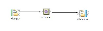
14.Press Ctrl+S to save the message flow. Figure 7 below shows one of the possible Message flows that takes single input:
Figure 7. Simple Message Flow with WTX Map node entertaining single Input.
Using the WTX Map node with a source map and multiple inputs
Develop a message flow with a WTX Map node specified with a source map, that at run time, is triggered to run by multiple inputs. The WTX Map node is used with a native Collector node, which gathers the multiple inputs and, when specified event criteria are satisfied, propagates the messages to the WTX Map node in the form of a message collection. For information about the Collector node and message collection.
The map can have many input cards. Any number of cards can receive data from the message collection, while any cards that do not receive data pull data directly from their adapter. The map can have many output cards. Cards that are connected to the message flow propagate data to the flow, while each of the unconnected cards sends data directly to their adapter. To develop a simple message flow that demonstrates this scenario, use the following steps. They assume that you used Map Designer to create a source map (.mms) file containing an executable map with two input cards, and one or more output cards.
1.Create a new message flow project in the Message Broker Application Development perspective.
2.Create a new message flow in the project. Select Use default broker schema, or provide your own schema name to qualify the message flow name.
3.Drag a WTX Map node from the palette onto the canvas for your message flow. The node initially has no output terminals and one failure terminal.
4.Navigate to the Properties view.
5.On the Basic tab of the WTX Map node, select the source map.
6.Drag a Collector node to the left of the WTX Map node.
7.Drag an input node, such as a FileInput node or an MQInput node, to the left of the Collector node.
8.Configure the input node with the necessary transport-related properties.
9.On the Input Message Parsing tab of the input node, configure the message template properties to describe the format of the input message. Select the domain from the list of supported message domains.
10.Right-click the Collector node and select Add Input Terminal. Enter the name of a new input terminal, which must match the card name of the input card in the map that receives the input message. The new input terminal is added to the Collection Definition table on the Basic tab. The broker's trace file lists any Collector input terminals that cannot be matched to input cards.
11.On the Basic tab, configure the required event criteria properties for the new input terminal, namely Quantity, Timeout, Correlation Path, and Correlation Pattern.
12.Connect the out terminal of the input node to the new input terminal on the Collector node.
13.Repeat steps 7 through 12 for each different input that the map requires from the message flow.
14.On the Basic tab of the Collector node, configure the Collection Name and Collection Expiry properties. In particular, specify a Collection Expiry value.
15.Connect the out terminal from the Collector node to the in terminal of the WTX Map node. Messages from the propagated message collection override the adapters of the map's input cards.
16.Connect the expiry terminal from the Collector node to the in terminal of the WTX Map node, to handle incomplete message collections.
17.Drag an output node, such as a FileOutput node or an MQOutput node, to the right of the WTX Map node, and connect one of the output terminals of the WTX Map node to the in terminal of the output node. Connecting the output terminal overrides the adapter of the corresponding output card.
18.Configure the output node with the necessary transport-related properties.
19.On the Outputs tab of the WTX Map node, configure properties to describe the format of the output message propagated by the output card:
1.Click Add to add a set of properties. The Add Properties entry dialog opens.
2.Enter values for Card Number, Message Domain, Message Set, Message Type, Encoding, and Coded Char Set Id, and click OK. Message Domain must be one of the supported message domains.
20.Repeat steps 17 through 19 for each output terminal that you want to connect.
21.Press Ctrl+S to save the code. An Unconnected catch terminals warning message appears, which you can ignore.
Using the WTX Map node with a precompiled map and multiple inputs
Develop a message flow with a WTX Map node specified with a precompiled map, that at run time, is triggered to run by multiple inputs. The WTX Map node is used with a native Collector node, which gathers the multiple inputs and, when specified event criteria are satisfied, propagates the messages to the WTX Map node in the form of a message collection. For information about the Collector node and message collection.
The map can have many input cards. Any number of cards can receive data from the message collection, while any cards that do not receive data pull data directly from their adapter. The map can have many output cards. Cards that are connected to the message flow propagate data to the flow, while each of the unconnected cards send data directly to their adapter. To develop a simple message flow that demonstrates this scenario, use the following steps. They assume that you used Map Designer to create a source map (.mms) file containing an executable map with one or more input cards and one or more output cards, and that you compiled the map for a target platform, creating a compiled map (.mmc) file.
1.Create a new message flow project in the Message Broker Application Development perspective.
2.Create a new message flow in the project. Select Use default broker schema or provide your own schema name to qualify the message flow name.
3.Drag a WTX Map node from the palette onto the canvas for your message flow. The node initially has no output terminals and one failure terminal.
4.Navigate to the Properties view.
5.On the Basic tab of the WTX Map node, select the precompiled map.
6.Drag a Collector node to the left of the WTX Map node.
7.Drag an input node, for example, a FileInput node or an MQInput node, to the left of the Collector node.
8.Configure the input node with the necessary transport-related properties.
9.On the Input Message Parsing tab of the input node, configure the message template properties to describe the format of the input message. Select the domain from the list of supported message domains.
10.Right-click the Collector node and select Add Input Terminal. Enter the name of a new input terminal, which must match the card name of the input card in the map that receives the input message. The new input terminal is added to the Collection Definition table on the Basic tab. The broker's trace file lists any Collector input terminals that cannot be matched to input cards.
11.On the Basic tab, configure the required event criteria properties for the new input terminal, namely Quantity, Timeout, Correlation Path, and Correlation Pattern.
12.Connect the out terminal of the input node to the new input terminal on the Collector node.
13.Repeat steps 7 through 12 for each different input the map requires from the message flow.
14.On the Basic tab of the Collector node, configure the Collection Name and Collection Expiry properties. In particular, you should specify a Collection Expiry value.
15.Connect the out terminal from the Collector node to the in terminal of the WTX Map node. Messages from the propagated message collection override the adapters of the map's input cards.
16.Connect the expiry terminal from the Collector node to the in terminal of the WTX Map node, to handle incomplete message collections.
17.Drag an output node, such as a FileOutput node or an MQOutput node, to the right of the WTX Map node, and connect one of the output terminals of the WTX Map node to the in terminal of the output node. Connecting the output terminal overrides the adapter of the corresponding output card.
18.Configure the output node with the necessary transport-related properties.
19.On the Outputs tab of the WTX Map node, configure properties to describe the format of the output message propagated by the output card:
1.Click Add to add a set of properties. The Add Properties entry dialog opens.
2.Enter values for Card Number, Message Domain, Message Set, Message Type, Encoding and Coded Char Set Id, and click OK. Message Domain must be one of the supported message domains.
20.Repeat steps 17 through 19 for each output terminal that you want to connect.
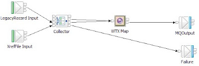
21.Press Ctrl+S to save the code. An Unconnected catch terminals warning message appears, which you can ignore. Figure 8 below shows one of the possible message flows that takes multiple input:
Deployment on Message Broker runtime
When you deploy message flows that contain WTX Map nodes, you must also deploy the associated WebSphere TX maps, and any files that the maps require. If the map is deployed to the broker in a map archive (MAR) file, you must make sure that any required files reside in the same project as the map, so they are automatically included in the MAR file. If the map is manually deployed to the broker, you must also manually deploy any required files to the broker. In particular, if your data is XML, and you have imported an XML Schema (.xsd file) when creating a type tree validated using Xerces, or have used an XML Schema directly when creating a map card, then the .xsd file is required by the map, and it must be deployed to Message Broker for use at run time in either of the following cases:
•If the data is being received from the message flow in the BLOB domain
•If the data is being received from a WebSphere TX adapter
At design time, you can specify the following map information on the WTX Map node. The two alternative map deployment mechanisms are described below:
•Using a source map with a WTX Map node
◦When Message Broker adds the message flow containing the WTX Map node to a BAR file, the specified executable map is compiled automatically to create a compiled map (.mmc) file.
◦The compiled map, and other files in the project, is zipped into a MAR file, which is added to the BAR file. The map is, therefore, automatically deployed to the broker when you deploy the message flow.
•Using a precompiled map with a WTX Map node
◦When Message Broker adds the message flow containing the WTX Map node to a BAR file, the map is not automatically compiled, and is not added to the BAR file.
◦You must manually deploy the map to the location that you specified.
At deployment time, you can specify the location of a compiled map by using the Configure tab in the Properties view, which is under the Manage tab in the Broker Archive editor. This setting overrides the map that you specified at design time.
At run time, your message flow can dynamically specify the location of a compiled map and pass it to the WTX Map node by using the Local Environment message tree. This setting takes precedence over any of the other methods.
Running the message flow
You can run the message flow by sending one or more messages through it. The message flow receives a message in an input node, which parses the message bit stream using the specified parser, creating a broker message tree. The resulting message tree is propagated down the flow. When a WTX Map node receives a propagated message tree, it runs the associated map and creates output messages.
If your map is expecting multiple inputs, use a Collector node to gather those inputs. In this case, you must send as many messages as are needed to complete the message collection defined by the Collector node. The body of a message tree, propagated from an output terminal of a WTX Map node, is owned by the message domain that you specified on the output terminal. Any headers present in the input message tree that the map received, such as MQMD, will be preserved unchanged in the propagated message tree. If the map received a message collection as its input, the propagated headers will be those of the first message in the collection. Headers from other messages in the collection are discarded. The Environment, Local Environment, and Exception List trees from the input message are also propagated unchanged.
If a failure occurs when running a map, the failure is added to the Exception List, and the input message, Environment, Local Environment, and Exception List are propagated from the failure terminal, if connected. Otherwise, an exception is thrown. When the message tree reaches an output node, it is serialized into a bit stream by the owning parser.